|
|
 |
Bus rapid transit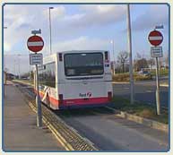 Taxonomy
and description Taxonomy
and description
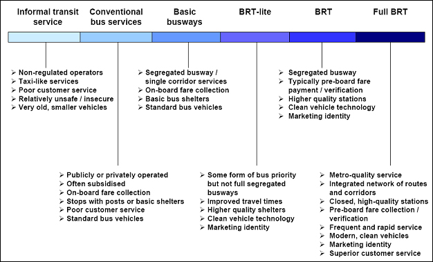
According to Levinson et al (2003, p12) Bus Rapid Transit (BRT) is “a flexible, rubber-tired rapid-transit mode that combines stations, vehicles, services, running ways, and Intelligent Transportation System (ITS) elements into an integrated system with a strong positive identity that evokes a unique image.” Similarly, Wright and Hook have pointed out that BRT “is a high-quality bus based transit system that delivers fast, comfortable, and cost-effective urban mobility through the provision of segregated right-of-way infrastructure, rapid and frequent operations, and excellence in marketing and customer service.” (Wright and Hook, 2007: p11). Levinson et al (2003) give the following seven identifying characteristics of a bus system that constitute a BRT system (Table 1) Table 1: Identifying Characteristics of Bus Rapid Transit Systems
Source: Levinson et al (2003) p 13. From Table 1, it is clear that BRT is intended to integrate all these component elements and technology to provide a high quality public transport package. All these various elements are intended to reduce the total journey time associated with a bus journey and to provide an improved level of service over conventional bus services. Provision of individual elements on their own does not generally qualify the system as a Bus Rapid Transit (Wright and Hook, 2007). Design of the right of wayThere are two primary forms of providing the required level of segregation required for operation of the bus services:
However the provision of bus lanes or guideways alone will not qualify the system as a BRT system. Figure 1 shows the spectrum of BRT systems and the primary distinction between conventional bus services to a full BRT system.
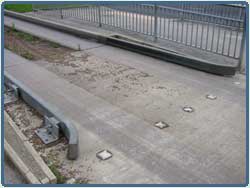
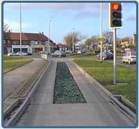
TechnologyIn this summary of the technological options for guided bus systems, the focus is primarily on guided systems since information on bus lanes and bus ways can be found under a separate note on bus priorities. Guided bus systems involve taking the steering of the bus off the bus and away from the bus driver for all or, more usually, part of the route. In doing so, they eliminate the need to allow for any lateral movement of the bus within a lane of traffic. A bus is generally approximately 2.5m wide, but a bus lane is usually 3.75m or even 4m wide to allow for this lateral movement. A guided bus system, therefore, provides opportunities to implement dedicated busways where road space is in short supply and, hence, where conventional bus lanes could be impractical. Depending upon the guidance technology used, systems may also provide opportunities to improve physical access to the bus by minimising the vertical and horizontal gaps between the bus stop and the bus. Some systems also provide for physical segregation from other traffic, making it impossible for other vehicles to block the guideway. They also provide for considerable flexibility in operations, in that a suitably adapted bus can travel on a guideway where this is available but can also travel on any other part of the road network as required. Types of Guided Bus Systems Whilst kerb guidance is the most commonly used system, there is a range of systems available or in development:
Kerb Guided Systems - to date, this is the most commonly used guidance technology. Specially equipped buses, with small 'guidewheels' positioned in front of the main front wheels, are guided along a track formed out of two vertical upstands (or kerbs), separated by the width of a bus axle (approximately 2.5m). On entering the track (or guideway), the guidewheels connect with the kerbs and guide the bus. Optical guidance - this is a more recent development in guidance technology and involves dashboard-mounted cameras, a video-monitoring system and a road- marking recognition system. Schemes are in operation in the Netherlands and Spain.
|